Weldlines occur in almost all injection molded parts and can potentially form weak spots. However, in many cases this risk can be mitigated by a proper a priori part design or mold design.
Mold filling simulation
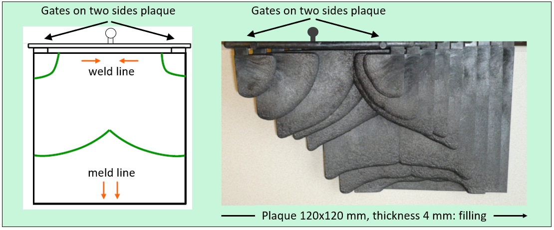
By moving the gate and, if possible, by changing the wall thicknesses, the path of the polymer melt in the cavity and thus the position of the weld line can be influenced. Since this is associated with changes to the mold, the effectiveness of the measure should be checked by first carrying out a Mold filling simulation.
The schematic on the right shows a schematic and experimental result of injection molding a plaque with the intent to create both a weldline and a meldline.


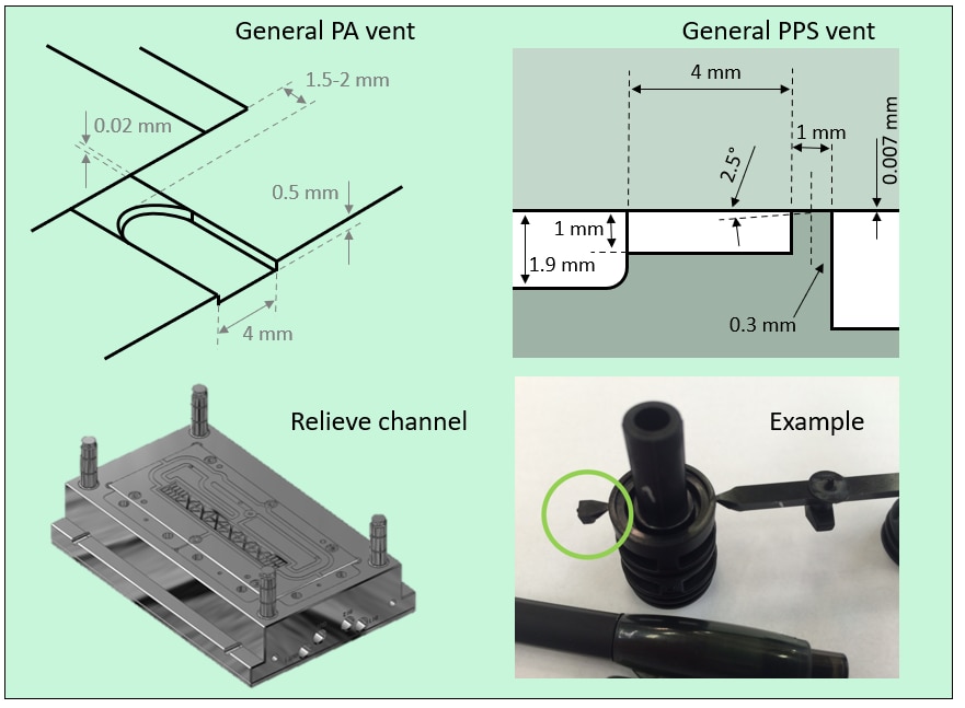
Venting location
Validate venting location to avoid air entrapment at the weldline location.
- Add/change the venting location if needed.
- Improve the venting in the affected areas of the mold to help filling.
- Make sure venting dimensions are adequate for the part and plastic used.
Number of gates
Make a conscious choice between single-point or multi-point gating. Potentially, move gate to improve flow conditions. An additional aspect to consider is to control timing of the gates.
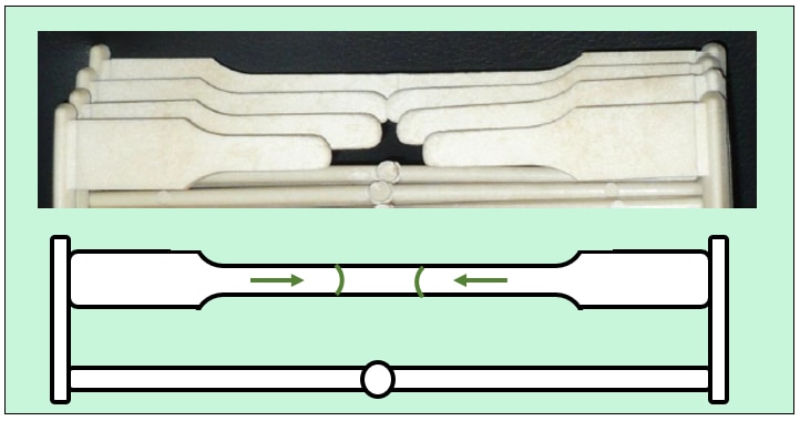
With one gate the tool design is easiest, but the operating freedom is very limited. Having multiple gates does not only change the melt flow, but also allows for variation of the timing.
The image and schematic on the right show an example of how the tensile bars with weldline have been injection molded. These tensile bars are used to estimate the weldline strength, provided in this tool.


Through-flow
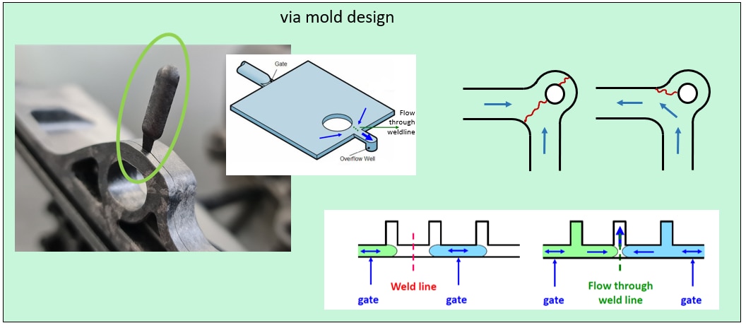
Create through-flow at the weldline location. This can be achieved in various ways:
- Via an overflow (see image): A 'meld-line' is stronger compared to a head-on weldline.
- Via part design: Think about (or simulate) the mold flow in advance. Asymmetry may help to place critical locations away from the weldline.
- Via equipment choice: Multi-component molding (possibly with backflow) or piston-driven SCORIM (Shear Controlled Orientation in Injection Molding) equipment can create a forced through-flow.