

Envalior
Corrugations, ribs and gussets
By applying corrugations, ribs or gussets to a parts functional geometry, its structural performance can be improved.
Corrugations, ribs and gussets
Function
If the load-carrying ability or the stiffness of a plastic part needs to be improved, it is necessary to either increase its sectional properties or change the material. Sometimes, it may be enough to change the material grade, for example using a higher glass fiber content. If that doesn’t suffice or isn’t desired for other reasons, increasing the sectional properties is often the solution.
In many cases, the simplest way to improve the sectional properties is increasing the part’s wall thickness. However, as is mentioned here, this has its limitations. Additional reinforcement can be obtained by adding corrugations or placing ribs perpendicular to the parts wall. Adding corrugations typically has a smaller impact on part weight and cooling time, but adding ribs has a bigger potential in terms of increasing the stiffness. Moreover, ribs allow for the facing or mating surface of a part to be smooth, which can be beneficial for aesthetic or functional reasons.
Corrugations
Adding corrugations to the design can stiffen flat surfaces in the direction of the corrugations (see Figure 1). They are very efficient and do not add large amounts of extra material or lengthen the cooling time. The extra stiffness is a result of increasing the average distance of the material from the neutral axis of the part, i.e. increasing the second moment of inertia.

Figure 1 - Corrugations
Rib dimensioning
When adding ribs, the following guidelines for dimensioning should be applied (see Figure 2):
- The thickness of the rib should be approximately 50 to 60% of the general wall thickness of the part. Exceeding this value may lead to sink marks on the surface opposite the ribs. Moreover, it can negatively influence material flow during injection, possibly resulting in weldlines and voids.
- The rib height should not exceed three times the general wall thickness as deep ribs become difficult to fill and may stick in the mold during ejection.
- On the sides of ribs, a draft angle of 1 - 1.5 degree should be applied. This means that the ribs are slightly tapered, becoming slightly thinner towards the top. This makes ejection of the part from the mold easier. On low ribs and in exceptional cases, a smaller or even no draft angle is acceptable. It should be noted though, that this may lead to cosmetic defects like scuff marks or issues with ejecting the part after molding.
- At the base of the rib, where it intersects with the nominal wall, a radius of 25 - 50% of the general wall thickness should be included. A minimum radius of 0.4 mm is suggested. This will eliminate a potential stress concentration and improve flow and cooling characteristics around the rib. When exceeding the 50% value, a material mass develops, increasing the risk of molded-in residual stresses, voids or sink marks.
- Spacing between two parallel ribs should be at least two times the general wall thickness. This prevents the mold from developing a hot blade that is fragile and has cooling problems.
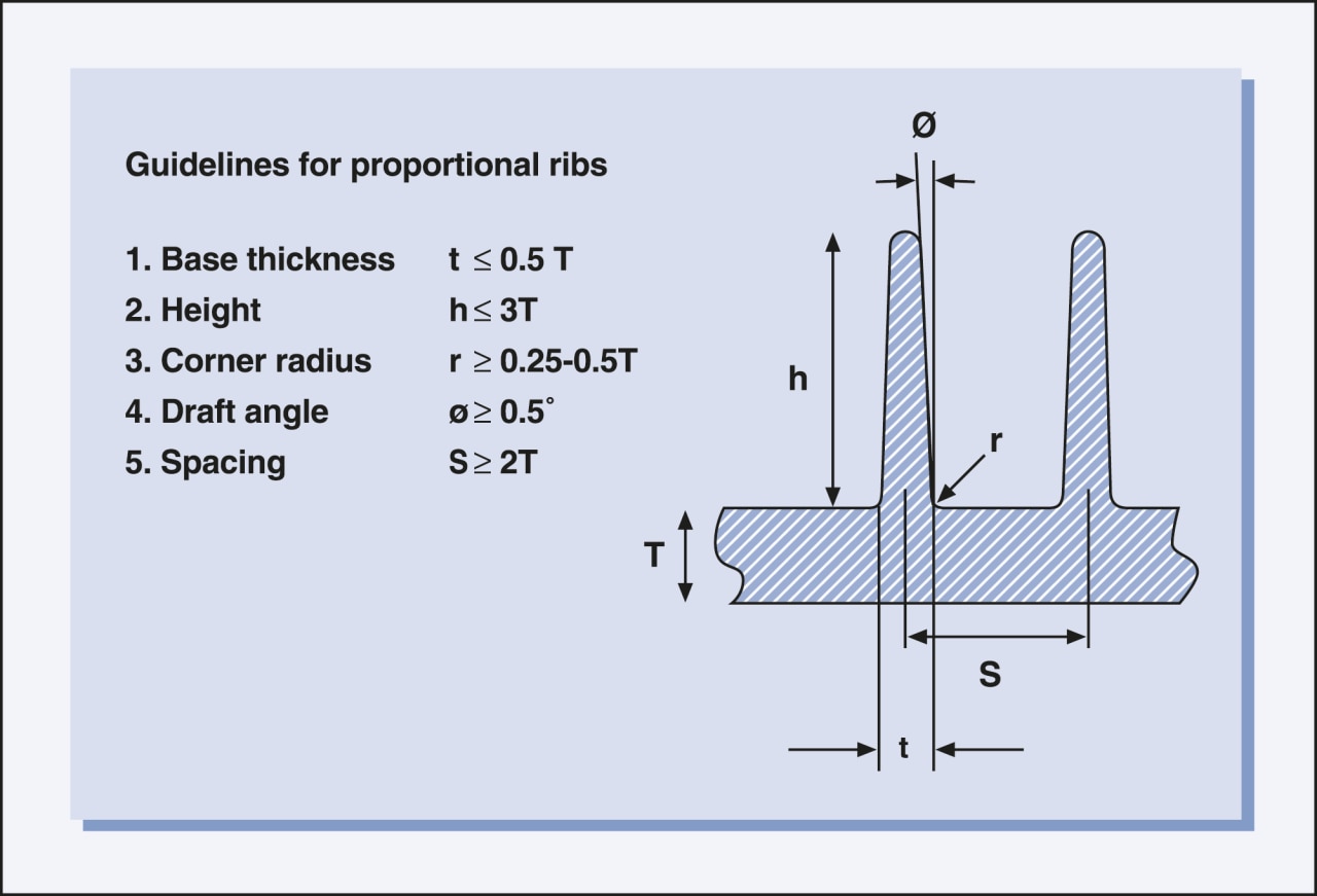
Figure 2 - Recommendations for rib dimensions
Rib placement
When placing ribs, the following guidelines for placement should be followed (see Figure 3):
- Ribs are preferably designed parallel to the melt flow as flow across ribs can result in a branched flow leading to trapped gas or hesitation. Hesitation can increase internal stresses and short shots.
- Parallel ribs should be spaced at a minimum distance of twice the nominal wall thickness; this helps prevent cooling problems and the use of thin blades in the mold construction.
- Ribs should be orientated along the axis of bending in order to provide maximum stiffness. Consider the example in Figure 3, where a long thin plate is simply supported at the ends. If ribs are added in the length direction, the plate is significantly stiffened. However, if ribs are added across the width of the plate, little improvement is found.
- When adding ribs to a profile or boxed section, their placement and orientation has a large impact on the obtained additional stiffness. This is visualized in Figure 4.
- For maximum performance and function, the neutral lines of the ribs and profile wall should meet at the same point. However, depending on the specific dimensions and material of choice, sink marks may occur. This can be avoided but will result in a weaker geometry:
- If the diagonal ribs are moved slightly apart, the rigidity is reduced 35%.
- If a short vertical rib is added to the design, the torsional rigidity is reduced an additional 5% (see Figure 5).
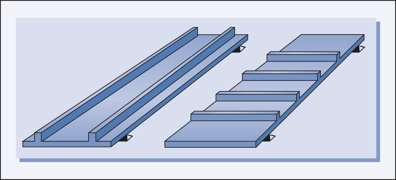
Figure 3 - Rib orientation.
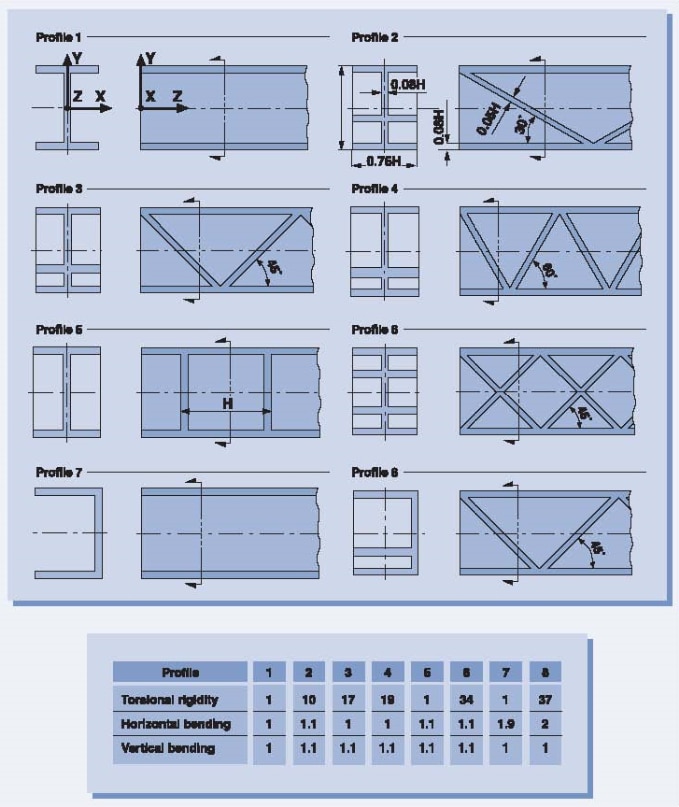
Figure 4 - Comparison of profiles in terms of torsional rigidity and bending.
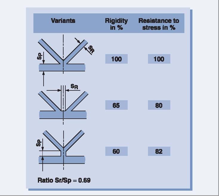
Figure 5 - Torsional rigidity and resistance to torsional stress as a function of the way in which the ribs are connected to the profile.
Gussets
Gussets can be used to reinforce corners, side walls and bosses. They can be considered as a subset of ribs, meaning that the guidelines for rib dimensioning and placement are also valid for gussets (see Figures 6 and 7).
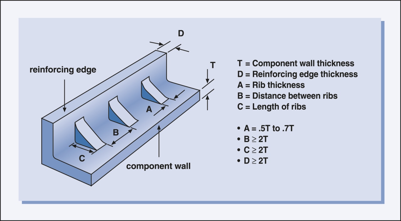
Figure 6 - Guidelines for gussets.
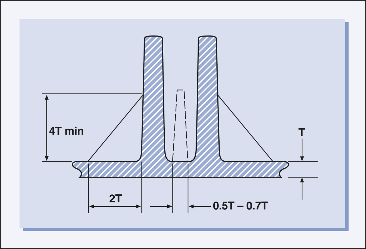
Figure 7 - Height of the gusset.