

Envalior
Holes
A hole in a part can have many functions, including acting as a fixation point, offering passage to other parts and reducing a parts weight.
Holes
Hole shape
The most convenient hole shape is a circular hole. The core pin required, is a common part available in many different sizes and materials. Using core pins also offers some flexibility as replacing a core pin for a slightly bigger or smaller one often only requires minor tool modifications.
Obviously, holes can’t always be circular, and they don’t need to be. Differently shaped holes can be made using custom cores.
From a tool manufacturing point of view, it’s easiest to create a hole with a centerline parallel to the draw direction of the tool. The simple construction of a static core makes it sturdy, low-maintenance and relatively cheap.
Holes with an axis that isn’t parallel to the mold opening direction, are mostly made using retractable pins or split tools. Core pins should be draw polished and include draft to facilitate ejection. In some cases, retractable cores can be avoided: if the part design allows for an extreme taper in the wall, a hole perpendicular to the draw direction can be formed by the main static core.
A hole may be a through hole (or ‘thru-hole’) or a blind hole. A through hole goes all the way through a part's wall. In other words, there’s an opening on both sides. A blind hole, however, has a specific depth, it doesn’t break through to the other side of the workpiece.
Whether the hole goes all the way through or not makes a big difference from a manufacturing point of view. If it does, the core can be supported on both ends. The longer and/or thinner a core is, the more important this is. A core supported on both sides is less likely to bend or even break during injection molding.
When molten material flows around a core pin during injection molding, a weldline occurs on the opposite side of where it first reaches the core. If weldlines are not permissible due to strength or appearance requirements, holes may be partially cored to facilitate drilling as a post-molding operation.
Hole dimensioning
As mentioned above, the length of the core pin, and therefore the depth of the hole, is limited by the ability of the core pin to withstand any deflection imposed on it by the melt during the injection phase. Through holes can be longer than blind holes because their core can be supported on both sides of the mold cavity. The following are some general guidelines for hole dimensioning:
- The depth of a blind hole should not exceed three times the hole diameter (see Figure 1).
- For smaller holes, diameters less than 5 mm, the depth over hole diameter ratio is 2.
- For blind holes the thickness of the bottom should be greater than 20% of the hole diameter in order to eliminate surface defects on the opposite surface. The more uniform the wall thickness remains, the better (see Figure 2).
- For through holes the length of a given core size can be twice that of a blind hole (see Figure 3).
- In cases where even longer cores are required, careful tool design is necessary to ensure balanced pressure distribution on the core during filling to limit deflection.
- The distance between two holes or one hole and the parts edge should be at least two times the part thickness or two times the hole diameter, whichever is the largest (see Figure 4).
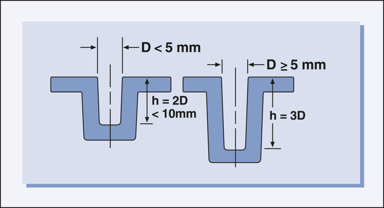
Figure 1 - Blind cores
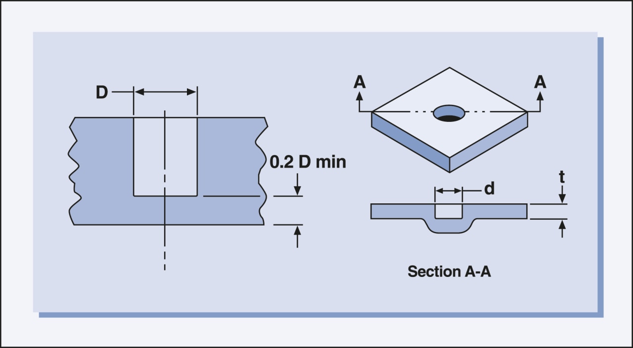
Figure 2 - Blind hole design recommendations

Figure 3 - Through cores
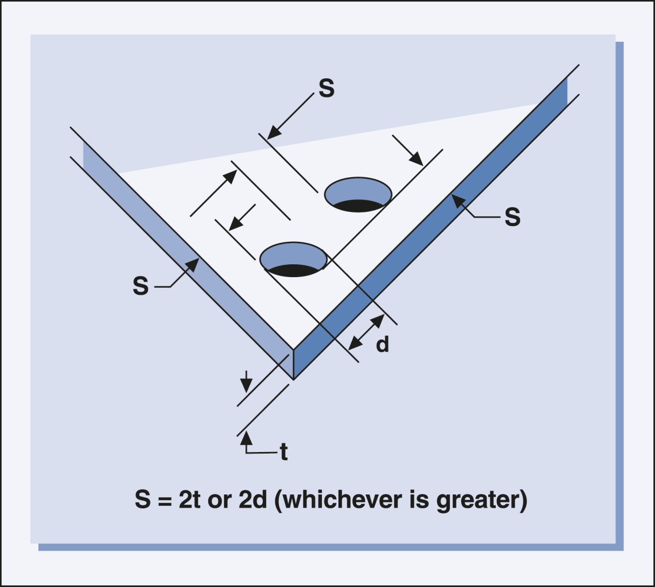
Figure 4 - Minimum hole spacing dimensions