

Envalior
Draft angle
Part surfaces parallel to the draw direction of the mold should be tapered to facilitate ejection of the part after molding.
Draft angle
Function
Since thermoplastics shrink as they cool, they grip to cores or male forms in the mold. This makes ejection difficult and may lead to scuff marks on the part. To facilitate ejection, part surfaces parallel to the draw direction of the tool require taper or draft. This draft allows the part to break free by creating a clearance as soon as the mold starts to open. The amount of draft needed depends on several factors:
- Material shrinkage – Some materials shrink more than others. In general, the higher the shrinkage, the larger the draft angle needed to prevent ejection issues.
- Height and shape of wall or feature – A shallow single straight rib having not enough draft causes less problems than a high cylindrical wall.
- Surface texture – A polished surface requires a smaller draft angle than a surface that is textured.
- Aesthetic requirements – Scuff marks might not be as big of a problem on a technical part "hidden" in an assembly while, for the cover part of the assembly, they may be totally unacceptable.
Taking into account the above factors, the guideline for draft angle dimensions is as follows (see Figure 1):
- Typically, one to three degrees draft is recommended.
- For untextured surfaces, generally a minimum of 0.5 degree draft per side is recommended.
- For textured sidewalls use an additional 0.4 degree draft per 0.1mm depth of texture.
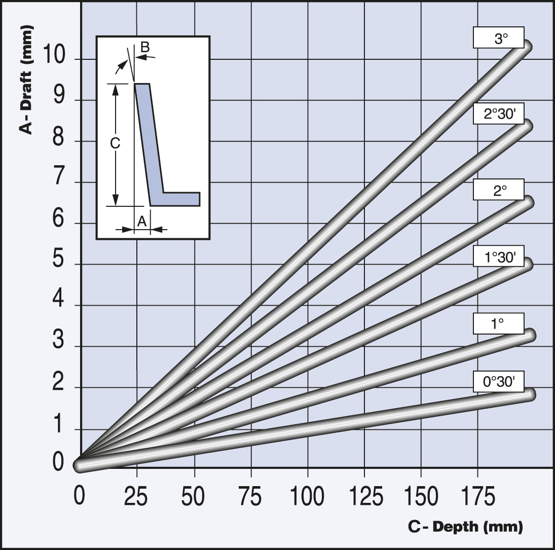
Figure 1 - Draft (A) in mm for various draft angles (B) as a function of molding depth (C)
Draft for shut-off
The most straightforward mold construction is where the parting plane of the mold halves is a flat surface perpendicular to the draw direction (see Figure 2). This setup also offers the easiest way to make sure that there is no gap between the mold halves when they’re closed. After all, the clamping force of the injection molding machine acts perpendicular to the parting plane. However, it’s not always possible or even beneficial to keep the parting plane flat.
In case of such a stepped parting line, the parting line jumps from one level to another. The surface needed to bridge these levels is called a shut-off because it’s where the mold halves shut against each other. The shut-off should never be exactly parallel to the draw direction. This leads to drag, causing the tool to wear over time. In a worst case scenario, misalignment during mold closing can cause significant damage. Instead, draft should be applied to guarantee proper shut-off.
On stepped parting surfaces, apply a draft of seven or more degrees. Five degrees should be considered as a minimum.
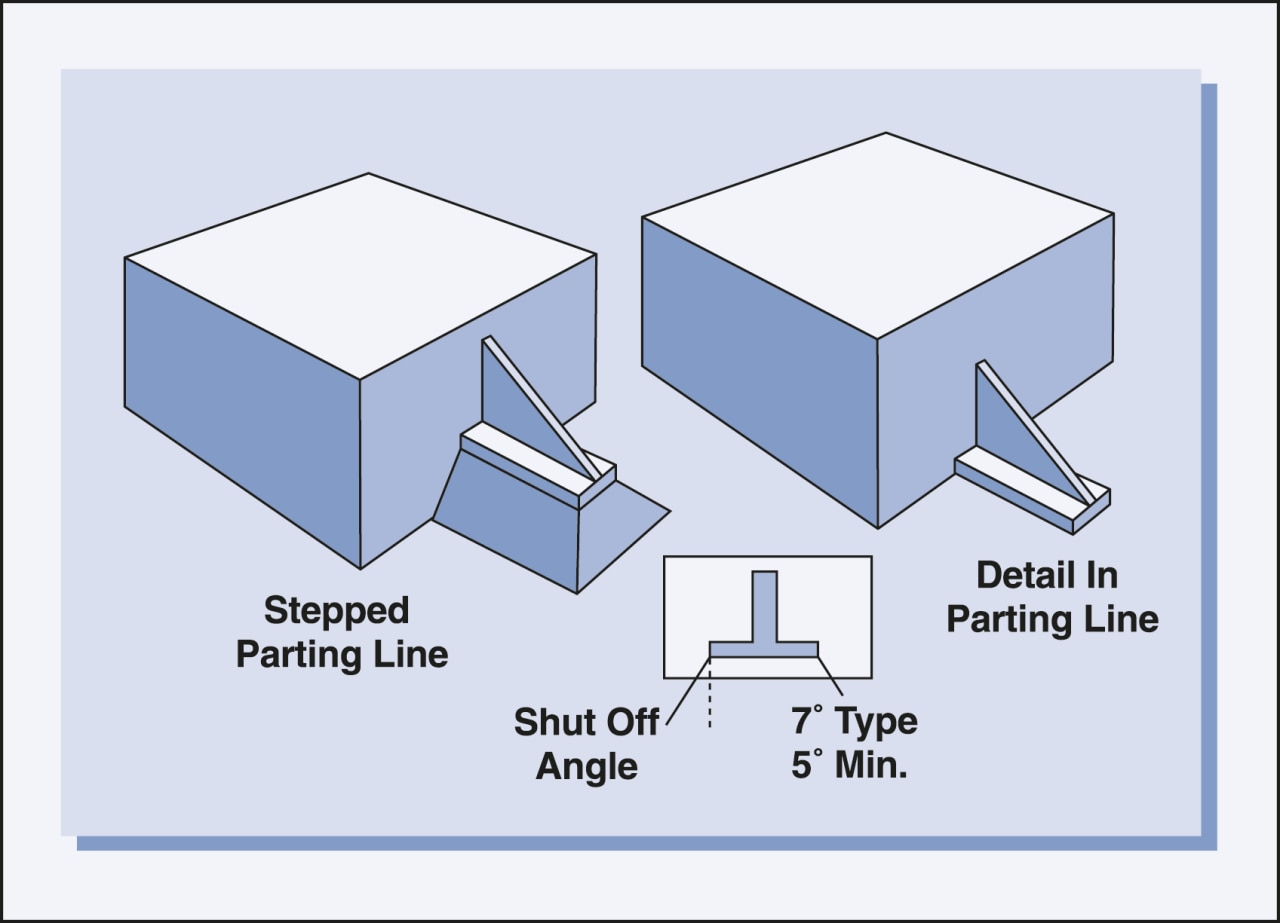
Figure 2 - Stepped versus flat parting line.